Working Principle Of Main Components Of Sewage Suction Truck
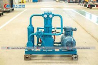
As we all know, the vacuum pump of the fecal suction / sewage suction truck is the key component of the fecal suction truck. It cooperates with the power take-off, the three-way four-position valve, etc. to realize the vacuuming and pressurization of the tank.
At present, single-stage rotary oil seal vacuum pumps are commonly used on fecal suction trucks. The vacuum pump is mainly composed of a pump body, a rotor and its assembly, a pump casing, a rotary vane, a slip ring, a bearing cover and a sealing device. The rotor is a wearing part. Disassembly and repair, the center of rotor rotation deviates from the center of the pump body. Its working principle is that the eccentric rotor works under the drive of the power take-off, and the tank is sucked into the compression chamber. When the pressure exceeds the specified value of the exhaust port, the compression chamber automatically opens and the compressed air is discharged, so that the air inside the tank is drawn out. After repeated cycles, a vacuum is formed inside the tank. In order to ensure the normal operation of the vacuum pump and avoid pollution, an oil-gas separator and a water-gas separator are also installed to filter the water vapor and oil-gas in the compressed gas during the production of the suction truck.
Water vapor separator
The water-gas separator is located at the top of the front of the tank, and the rear of the tank is open. It has a gas pipe with rectangular holes on both sides of the pipe for air to enter and leave the tank. During the suction operation, the air in the container comes out of the rectangular hole, the volume suddenly expands, and the flow rate decreases, so that the water molecules and air are separated, which can reduce the harm to the lubricant and the machine parts.
Oil and gas separator
The compressed air discharged from the vacuum pump has a high speed and carries a large amount of oil droplets when it breaks through the oil film layer. In order to reduce oil consumption and prevent pollution, an oil and gas separator is installed. The oil and gas separation is located in the middle right of the manure truck frame, with a vacuum pump at the front and back to the oil tank. An oil retaining pipe is provided in the oil-gas separation. When compressed air enters, its volume suddenly expands, the flow velocity decreases, changes the flow direction, and flows out through the porous oil retaining pipe. Due to the reduced flow velocity of the oil and gas molecules, the impact on the wall and the hole wall is increased. On the vessel wall, condensed button-shaped oil droplets, along the vessel wall and the overflow pipe flow into the oil return tank, and the compressed air after the initial purification flows to the top of the oil return tank.
PTO
The operation of the power take-off of the suction truck depends on the power of the engine to rotate through the power take-off and the transmission shaft. The power take-off is installed on the left or right side of the transmission.
This power take-off is composed of an input gear, an input shaft, an intermediate gear, an intermediate shaft, an output shaft, an output gear, a fork shaft, a fork shaft, etc., and an operating handle.
Four-way valve
The vacuum pump can only rotate counterclockwise (facing the front of the car). To draw in air from the tank or discharge air into the tank, a four-way valve is required.
The four-way valve communicates with the tank, vacuum pump, and return tank to the atmosphere. There is a partition in the four-way valve. Change the suction direction of the vacuum pump. When the four-way valve connects the tank to the vacuum pump, the excrement truck will perform the discharge operation.
Return tank
The oil return tank is located in the middle right part of the frame, with a left-hand oil separator and a four-way valve on the right.
There is an oil baffle in the oil return tank, and the inlet and outlet are not connected. At this time, the compressed air flowing from the oil and gas separator must pass through multiple obstacles before it can be discharged to the four-way valve. Because the volume of the oil return tank suddenly doubles, the air flow rate is obvious Lowering, coupled with obstacles such as the oil screen, the oil molecules in the compressed air intensify the bumps, attach to the inner wall and the mesh surface, then flow into the bottom, and the compressed air that has been purified again flows to the four-way valve.
Below the oil return tank, there is a straight plug, which can control the lubricating oil leaf supplied to the vacuum pump, and a liquid level tube, which can observe the oil storage quantity and oil quality.